David Zhang | Founder & CEO, ZPET (Shandong ZhongPi Machinery Equipment Co., Ltd.) | Published July 21, 2026
A craft brewery layout is fixed by four dimensions before any vessel is cut: ceiling clearance above the tallest tank, service clearance around each vessel, floor slope and drain position, and utility entry points. Get these onto a dimensioned drawing first. Workflow arrangement follows from them, not the other way round.

What the drawing has to settle before steel is cut
Most layout advice starts with flow: grain in one end, packaged beer out the other, cellar separated from the hot side. That advice is correct and almost useless once you are holding a signed order, because a fabricator cannot cut a shell from a flow diagram. Tank diameters, leg heights, manway orientation, jacket connection sides and racking arm positions all get frozen at drawing stage, and every one of them is a function of the building.
Compared with the workflow-first layout guidance that circulates on most equipment-vendor and hospitality-software blogs, a dimension-first drawing changes the order of decisions. The building is measured, the constraints are written down, and vessel geometry is designed to fit inside them. Reversing that order is how a brewery ends up with a 3,000 L (approx. 25 BBL) fermenter that clears the roll-up door but cannot be stood upright once inside.
Four categories have to be dimensioned and signed off:
- Vertical envelope: slab to lowest overhead obstruction, not slab to roof deck.
- Horizontal service envelope around each vessel and between vessel rows.
- Wet zone: floor slope, drain type and position, wall junctions.
- Utility entry points and routing, including the vertical drops.
Ceiling height: the constraint that reopens more projects than floor area
Floor area is easy to measure and easy to negotiate. Ceiling height is neither, and it is the constraint that most often forces a redesign after a lease is signed.
The number that matters is not the roof deck. It is the underside of the lowest thing in the way over the tank position: a sprinkler main, a duct run, a light fixture, a structural beam. Measure to that.
Required clearance above a fermenter is a stack, not a single figure:
- Overall tank height including legs and top-mounted fittings
- Vertical space for the CIP arm, pressure relief valve and any top manway to be opened and serviced
- Lifting headroom if the tank will be uprighted inside the building, which is the sling and hook height above the tank top, plus the hoist itself
That third item catches people. A tank that fits standing does not necessarily fit being stood up. If your ceiling is tight, the layout question is not “does the tank fit” but “where in this room is there one bay with enough height to rotate it from horizontal to vertical,” and that bay has to be on the path from the door to the final position.
Two practical outcomes when height is short: reduce tank diameter-to-height ratio and go wider rather than taller, or split the target capacity across more vessels. Both have consequences, discussed below.
How much space does each vessel actually need?
Service clearance is where layout drawings and reality diverge. Tanks are drawn as circles; hoses, operators, ladders and insulation contractors are not.
| Dimension | How to derive it | Planning range to check on the drawing |
| Clear space in front of the side manway | Manway door swing radius + one operator kneeling with a cleaning tool | 900–1,200 mm |
| Clearance behind / between adjacent tanks | Access for jacket connection, insulation cladding and weld inspection | 400–600 mm minimum |
| Aisle between two tank rows | Two operators passing with a hose reel, or a pallet truck if kegs move through | 1,000–1,500 mm |
| Clearance above tank top fittings | CIP arm removal + PRV service access | 400–600 mm above the highest fitting |
| Clearance under the racking / dump valve | Bucket, hose connection and yeast collection vessel | 350–500 mm below the valve |
| Brewhouse platform working depth | Operator plus grain-out access at the mash tun manway | 900 mm minimum walkway |
These are planning envelopes for the drawing stage, not published equipment specifications. Every one of them should be replaced by the actual figure on the general arrangement drawing for your order before the layout is treated as final.
A detail worth fixing early: manway orientation. Fermenters are usually specified with a side manway as an option, and which way it faces determines whether a row of tanks needs a wide aisle on one side only, or clearance on both. Deciding this at drawing stage costs nothing. Deciding it after the shells are rolled costs a re-fabrication.

Floors, slope and drains
The floor is the part of a brewery that cannot be retrofitted without shutting down, and it is routinely left to the general contractor with no brewing input.
Slope and drainage want to be resolved together. A common planning basis is a fall of roughly 1:50 to 1:100 toward a trench or point drain, with the trench positioned so that no wash-down water has to cross a walkway to reach it. Trench drains suit the cellar and brewhouse floor where volumes are high and spills are frequent; point drains are usually enough under a packaging line.
Sanitary design principles for the wet zone, including coving at wall-to-floor junctions, drainable surfaces and the avoidance of horizontal ledges that hold water, are set out in the 3-A Sanitary Standards (3-A Sanitary Standards, Inc.) and in ASME BPE for hygienic surfaces and surface-finish definitions (ASME Bioprocessing Equipment Standard). Those documents govern equipment, but the same logic applies to the room the equipment stands in: if the floor cannot be cleaned and dried, tank hygiene does not survive contact with it.
Drain sizing has one non-obvious driver. Peak flow is not wash-down; it is a fermenter dump or a full vessel emptied to drain in an emergency. Size for that event, or accept that it floods the aisle once.
Six utility runs to fix on the plan
Utilities are usually shown as a note on a layout drawing and discovered as a problem during commissioning. Each of these needs a defined entry point, a route and a termination position:
- Electrical supply.Confirm voltage, phase and frequency at the drawing stage. Control panels engineered for the North American market to UL/cUL requirements differ from those built for European or Australian installations, and the panel enclosure position affects the layout because it needs clear working space in front of it.
- Steam or heating source.Brewhouses can be steam, electric or direct fire heated. Steam requires boiler room location, pipe routing with fall for condensate return, and a decision on whether the boiler is inside the production room or in a separate space with its own ventilation and code requirements.
- Chiller position, glycol main routing and the drop to each tank jacket. Long runs cost temperature stability; a chiller placed outdoors for noise reasons buys quiet and pays for it in line losses.
- Hot liquor and cold liquor.Tank positions, plus the fact that hot liquor tanks are often the tallest vessel in the room and therefore the ceiling-height driver rather than the fermenters.
- Bulk tank or cylinder bank location, gas line routing and low-level ventilation for the cellar. CO2 accumulates at floor level and cellars are where people work alone.
- Potable water in and waste out.Backflow prevention position, and the waste connection point, which frequently sits where the building’s existing service happens to be rather than where the brewery would like it.
Brewhouse and fermentation tank dimensions that go on the ZPET drawing
Layout planning stops being generic once the equipment configuration is chosen, because the configuration changes the footprint significantly.
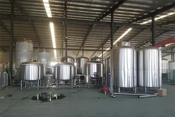
Brewhouse Systems — 2-vessel to 5-vessel configurations. A 2-vessel system combines functions and occupies less floor area, at the cost of longer brew days and less overlap between batches. A 4- or 5-vessel system separates mash tun, lauter tun, kettle and whirlpool, shortening turnaround and increasing daily batch count, and it needs correspondingly more floor space and a larger operating platform. Heating is specified as steam, electric or direct fire, and that choice feeds straight back into the utility plan above.
Capacity tiers and what they mean for the room. Nanobrewery systems of 1–5 BBL suit brewpubs and taprooms where space is the binding constraint, and the modular arrangement is designed to fit small footprints. Microbrewery systems of 7–30 BBL are where cellar expansion planning matters most, because fermenter count grows faster than brewhouse size. Commercial systems of 40 BBL and above run PLC/HMI automation and are planned around continuous operation, which changes access requirements: maintenance clearance becomes as important as operating clearance.
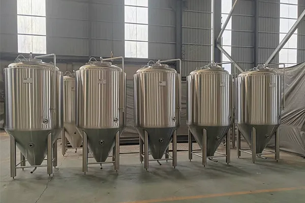
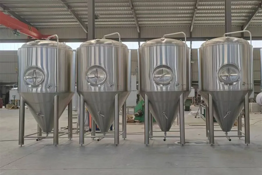
خزانات التخمير و خزانات البيرة اللامعة. Both are built in SS304 or SS316L sanitary grade with a 0.4 μm mirror-polished interior, dimple cooling jacket, optional side manway, and are pressure tested before shipment. Construction uses TIG double-sided argon arc welding, with a 24-hour pressure hold test and X-ray weld inspection as part of a 5-step QC sequence. Tanks carry a 10-year structural warranty.
Three of those specifications have direct layout consequences. The dimple jacket determines which side the glycol connections land on and therefore which way tanks should face in a row. The optional side manway sets the aisle width discussed earlier. The 0.4 μm interior finish is only meaningful if CIP coverage is complete, which depends on having the vertical clearance above the tank to service the CIP arm.
Every ZPET project starts with 3D brewery layouts, technical drawings and flow charts completed before the order, designed around the buyer’s actual building footprint and utilities. Systems are engineered to meet PED (CE), UL/cUL and AS1210 requirements, which matters at layout stage because pressure equipment placement, relief valve discharge routing and inspection access are part of what those frameworks address (EU Pressure Equipment Directive 2014/68/EU; AS 1210 Pressure Vessels, Standards Australia).
ZPET does not publish price lists or price ranges. Layout engineering and equipment are quoted per project, factory-direct without distributor markup. For a figure, a quotation is required.
Three floor-plan patterns, compared
| Pattern | Best suited to | Ceiling demand | Expansion behavior | Main drawback |
| Linear (brewhouse → cellar → packaging in one run) | Narrow, deep buildings; single roll-up door at one end | Uniform across the run | Extends at the packaging end only | Cellar growth blocks the packaging path once the run is full |
| L-shaped (cellar turns off the brewhouse axis) | Buildings with a structural core or offices occupying one corner | Can be lower over the cellar leg | Cellar leg extends independently | Longer glycol and CIP runs to the far leg |
| Central spine (utilities down the middle, vessels either side) | Wide, open-span buildings | Highest, because both sides share the tallest constraint | Adds tank rows outward from the spine | Requires the widest building; wasteful in narrow spaces |
Taprooms sit on top of this. If the taproom shares the production room, the layout has to add a public boundary, a separate route for kegs to the bar that does not cross the cellar working area, and a sightline decision about which vessels the public actually sees.

The mistake: designing around today’s tank count
The most expensive layout error is not a clearance that is too tight. It is a cellar sized for the fermenters being bought now.
A brewery that opens with four fermenters and doubles demand in eighteen months typically does not want a second brewhouse. It wants more fermenters, and it wants them on the existing glycol main. If the glycol header was sized and routed for four tanks, adding four more means re-piping the cellar or accepting temperature control that drifts under load. Reserve header capacity and stub connections at layout stage; the incremental cost is a fraction of the retrofit.
The related edge case involves buildings with a mezzanine or an uneven slab. Tank legs are cut to a fixed length. On a floor with a 40 mm variation across the cellar footprint, tanks stand out of plumb, which affects both drainage of the cone and the seating of the racking arm. Slab flatness across the tank positions should be surveyed before leg lengths are finalized, and adjustable feet or shims specified where the survey shows variation.
From building survey to approved drawing: nine steps
- Measure the slab dimensions and mark every column, drain, existing penetration and slope change on a scaled plan.
- Measure clear height at a minimum of four points, recording the lowest overhead obstruction at each tank position rather than the roof deck.
- Record door and access opening dimensions on the delivery path, including any turn radius from the street to the door.
- Confirm incoming electrical capacity, voltage, phase and frequency in writing from the supply authority or landlord.
- Locate the waste connection point and confirm the maximum discharge rate and any temperature limit the local authority imposes.
- Fix the target production capacity for year three, not year one, and derive fermenter count from that figure.
- Choose the brewhouse configuration and heating method, then position it against the utility entry points identified in steps 4 and 5.
- Place vessels using the service clearances in the table above, and check the uprighting path from door to final position at every point along the route.
- Issue the dimensioned layout for review, mark up changes, and approve a single revision as the fabrication reference. Verify that the approved revision number appears on the order.
Steps 1 through 5 are the buyer’s responsibility and cannot be delegated to the equipment supplier, because only the buyer can access the building. Steps 6 through 9 are where a fabricator’s drawing team earns its place.
What a dimension-first process costs you
This approach has real costs, and they are worth stating plainly.
It adds time before fabrication starts. Producing a 3D layout, circulating it, and getting approval takes weeks that a catalogue order does not. If a brewery is racing a lease clock, that delay is felt immediately and the payoff arrives much later.
It requires the buyer to produce accurate building measurements, including obstructions that most people never think to record. A survey done casually with a tape measure and no ladder produces a drawing that is precise and wrong.
It locks decisions early. Manway orientation, jacket connection side and leg height become expensive to change once the drawing is released to production. Buyers who prefer to keep options open until late in a project will find the process uncomfortable.
And it does not replace local professional review. A fabrication drawing is not a permit set. Fire separation, occupancy classification, mechanical ventilation and structural loading all need a locally licensed engineer or architect, and no equipment supplier’s layout substitutes for that.
الخطوة التالية
Before requesting a layout from any supplier, complete steps 1 through 5 above and put the results in a single document. That survey is the input that determines whether the drawing you receive back is usable or decorative, and it stays useful across every supplier you talk to. Two areas this guide has deliberately left out and which deserve separate treatment: packaging line layout, where can and keg line clearances follow different logic from tanks, and grain handling, where silo, auger and mill placement interact with dust control requirements that vary sharply by jurisdiction.
الأسئلة الشائعة
Q: What is the minimum ceiling height for a craft brewery?
A: There is no single figure, because it depends on tank geometry rather than capacity alone. Work it out as tank overall height plus top-fitting service clearance, and separately check whether the tank can be uprighted inside the building. Two 1,000 L (approx. 8.5 BBL) fermenters from different geometries can differ by half a metre in overall height.
Q: How much floor space does a brewery need per barrel of capacity?
A: Space-per-barrel rules of thumb are unreliable because fermenter count, not brewhouse size, drives cellar area, and fermenter count depends on turnaround time and beer styles. Derive floor area from a tank schedule for your year-three target instead. Capacity tier conventions in BBL follow Brewers Association usage.
Q: Should the brewhouse or the cellar be planned first?
A: The cellar, in most cases. It occupies more floor area, it grows over time, and its glycol and drainage requirements are harder to change later. The brewhouse position is then set relative to the cellar and the utility entry points.
Q: Can a layout be changed after the equipment order is placed?
A: Room arrangement can change. Vessel dimensions, manway orientation and jacket connections generally cannot, once fabrication has begun. This is why the drawing is approved by revision number before the order proceeds.
Q: Do I need trench drains or are point drains enough?
A: Trench drains are the usual choice for the cellar and brewhouse where wash-down volumes are high and spills are frequent. Point drains are often adequate under packaging equipment. Size for the worst case, which is a vessel emptied to drain, not routine cleaning.
Q: How much does a brewery layout and equipment package cost?
A: ZPET does not publish prices or price ranges. Cost depends on configuration, capacity, materials and destination market requirements, and is quoted per project. Contact us for a quotation.